Spatial Manager allows you to create text labels in the drawing from selected objects on the drawing or map. One of the improvements introduced in latest versions of Spatial Manager is the option to create labels of selected objects in the drawing using multiple data fields and properties of the objects to be labeled
In addition to this it is possible to set different representations (style, size, color, …), for each field of the created labels. Let’s take a closer look at the different options of this new feature
Available for AutoCAD, BricsCAD, ZWCAD and GstarCAD
1 - Start labeling
To start the labeling, click on the ‘Labels’ icon in the ‘Spatial Manager’ ribbon or execute the command ‘SPMLABEL’ in the command line
2 - Select objects to be labeled
Select the objects in the drawing to be labeled. The selection options are:
- All objects in the drawing
- Only selected objects in the drawing
- All objects in a layer
3 - Set the fields and properties to be labeled and their display options
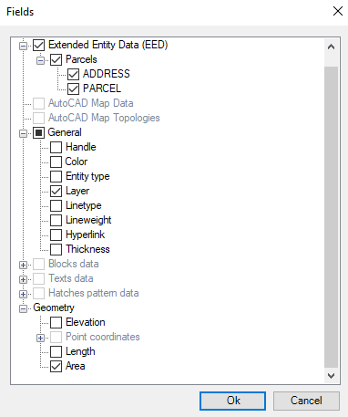
Now we must add the fields and properties of the objects we want to use to create the labels
Arrange them with the up and down arrows and, and the particular display options (font style, color, relative size, …), for the desired fields
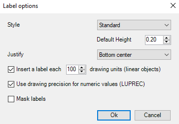
If necessary, set the global display options (font name, default size, justification, mask labels, …)
4 - Set general options
- Target layer
- Apply random colors if new layers are created
- Tread closed polylines as polygons (if checked the label will be created on the centroid, if not, multiple labels will be created over the perimeter)
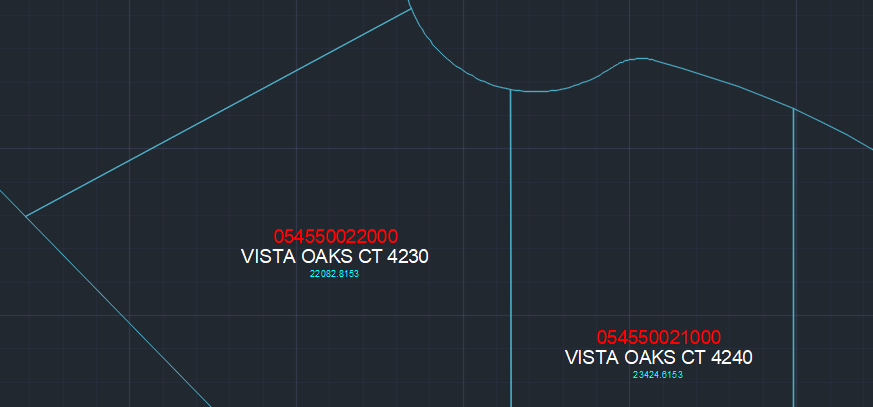
5 - Result


